Structural Design and Simulation of 3P Cantilevered Prostate Cancer Particle Implantation Robot
-
摘要:
基于前列腺癌患者截石位粒子植入手术的可操作空间,提出前列腺癌粒子植入机器人的设计要求;将机器人分为位置调整模块、姿态调整模块、末端植入器3个组成部分.通过杆件尺寸设计实现3自由度位置调整机构的运动解耦,计算其工作空间可满足临床需求;姿态调整模块采用远程运动中心(remote center of motion,RCM)机构,引入平行四边形机构解决运动死点问题;末端植入器采用齿轮齿条机构驱动外针,硬质摩擦槽轮驱动内针,通过弹簧压紧机构提供稳定压紧力并设计大容量粒子弹夹.最后,利用ADAMS进行运动学分析,验证数值计算的准确性;动力学分析验证前列腺癌粒子植入机器人设计的合理可行.
Abstract:Based on the operable space of prostate particle implantation surgery, the design requirements of prostate particle implantation robot were proposed. The robot was divided into three components: position adjustment module, posture adjustment module, and end implanter. Through the design of the size of the rod, the motion decoupling of the 3-degree-of-freedom position adjustment mechanism was calculated, and its working space was calculated to meet the small operation space and completely cover the prostate body; the attitude adjustment module adopted the RCM mechanism, and the parallelogram mechanism was introduced to solve the problem of motion dead point; the implanter used a rack and pinion mechanism to drive the outer needle and a hard friction groove wheel to drive the inner needle, which provided a stable compression force through the spring compression mechanism; and a large-capacity particle clip was designed. The kinematics analysis was carried out through ADAMS to verify the accuracy of the conclusions obtained in the numerical calculation part of the article, and the kinetic analysis was carried out to verify that the design of the prostate particle implantation robot was reasonable and feasible.
-
前列腺癌是男性生殖系统最常见的恶性肿瘤[1]. 放射性粒子植入技术具有靶向性强、无副作用、创伤小和疗效确切的特点. 传统放射性治疗过程中,医生直接操作尺寸庞大的手术器械,长时间的手术容易造成疲劳,质量下降,不能充分发挥医生的手术水平;并且手术操作复杂,年轻医生需要经过长期的学习和专业培训,成长周期长. 机器人技术和放射性治疗技术相结合会克服上述传统放射性治疗术的缺点.
近年来,Yu等[2]、Podder等[3]设计了单通道与多通道粒子植入机器人系统. Salcudean等[4]设计了一个4自由度的前列腺短距离放疗机器人. 文献[5]中Vaida等采用并联式结构,该结构设计不但具有导向板,还可以自由地调整植入针的进针角度. 姜杉课题组设计了一个6自由度基于核磁图像导航的前列腺针刺手术机器人[6]以及直角坐标式超声图像导航前列腺手术机器人[7]. 张永德等[8]提出了1P2R悬臂式及基于3-PCR并联式的前列腺癌粒子植入机器人系统,并进行了运动分析等相关工作. 现有机器人系统多为直角坐标式和并联式,但是直角坐标式体积庞大,运动灵活性较差;并联机构运动学反解复杂,控制难度大,具有运动奇异点;1P2R悬臂式机构需要进行重力补偿,局部结构变复杂且精准控制难度大.
本文基于模块化设计思想设计了杆件结构尺寸,得到了一种运动解耦的前列腺粒子植入机器人. 文中详细介绍各部分的结构设计,并对其运动学进行分析. 完成了机器人的运动学和动力学仿真,验证了所设计结构的合理可行.
1. 前列腺粒子植入机器人结构设计
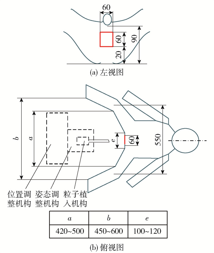
前列腺粒子植入过程中,患者采用膀胱截石位,可操作空间[9]如图 1所示.
采用模块化设计[10],分为3自由度的位置调整模块、2自由度的姿态调整模块、2自由度的粒子植入机构3个模块,彼此间的运动关系完全解耦,降低了控制难度.
1.1 位置调整模块设计
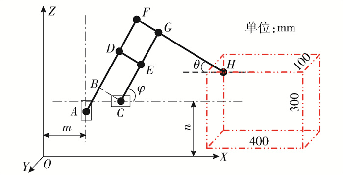
由图 1可以看出:竖直方向工作范围较大,水平方向工作范围较小. 结合SCARA型[11]和直角坐标型2种结构的优点,并进行融合后得到图 3所示的机构模型. 悬臂式位置调整机构的3自由度由3个移动副来实现.其中Y轴运动与XOZ平面内的运动相互解耦,而XOZ平面内的运动关系未知,因此建立坐标系如图 2所示,设各点坐标为:A(m, zA)、B(xB, zB)、C(xC, n)、G(xG, zG)、H(xH, zH). 根据平行四边形的结构特点,可得如下几何关系:
$$ B F=C G, B F\|C G ; B C=F G, B C\| F G $$ 令
$$ A B=a, B F=C G=b, B C=F G=c, G H=d $$ 则,B点的坐标可表达为如下2种形式:
$$ \left\{\begin{array}{l} x_{B}=m+a \cos \varphi \\ z_{B}=z_{A}+a \sin \varphi \end{array}\right. $$ (1) $$ \left\{\begin{array}{l} x_{B}=x_{C}-c \cos \theta \\ z_{B}=n+c \sin \theta \end{array}\right. $$ (2) 式中:θ为末端H点与X轴的夹角;φ为C点与X轴的夹角;m为A点X轴坐标;n为C点Z轴坐标.
由式(1)(2)联立,并整理解得
$$ \left\{\begin{array}{l} \cos \varphi=\frac{x_{C}-c \cos \theta-m}{a} \\ \sin \theta=\frac{z_{A}+a \sin \varphi-n}{c} \end{array}\right. $$ (3) 又因为H点的坐标表示为
$$ \left\{\begin{array}{l} x_{H}=x_{C}+b \cos \varphi+d \cos \theta \\ z_{H}=n+b \sin \varphi-d \sin \theta \end{array}\right. $$ (4) 将式(3)代入式(4)中并整理得
$$ \left\{\begin{array}{l} x_{H}=\left(1+\frac{b}{a}\right) x_{C}-\frac{b m}{a}+\left(d-\frac{b c}{a}\right) \cos \theta \\ z_{H}=-\frac{d}{c} z_{A}+\left(1+\frac{d}{c}\right) n+\left(b-\frac{d a}{c}\right) \sin \varphi \end{array}\right. $$ (5) 直接求解等式(5)比较困难,在结构设计时可实现
$$ \left\{\begin{array}{l} d-\frac{b c}{a}=0 \\ b-\frac{d a}{c}=0 \end{array}\right. $$ (6) 解得
$$ a d=b c $$ (7) 将式(6)代入式(5)解得
$$ \left\{\begin{array}{l} x_{H}=\left(1+\frac{b}{a}\right) x_{C}-\frac{b m}{a} \\ z_{H}=-\frac{d}{c} z_{A}+\left(1+\frac{d}{c}\right) n \end{array}\right. $$ (8) 杆长参数取值应满足式(7),杆长参数具体取值如下:
$$ \left\{\begin{array}{l} a=100 \mathrm{~mm} \\ b=300 \mathrm{~mm} \\ c=100 \mathrm{~mm} \\ d=300 \mathrm{~mm} \end{array}\right. $$ (9) 将等式(9)代入式(8)中,得
$$ \left\{\begin{array}{l} x_{H}=4 x_{C}-\frac{b m}{a} \\ z_{H}=-3 z_{A}+\left(1+\frac{d}{c}\right) n \end{array}\right. $$ (10) 式中m、n、a、b为常量,所以xH只与xC有关,zH只与zA有关. 即C点的横坐标决定了末端点H的横坐标,A点的纵坐标值决定了H点的纵坐标,由于A、C两点运动独立,因此H点在X轴与Z轴的运动解耦.
将式(9)代入式(10)得
$$ \left\{\begin{array}{l} x_{H}=4 x_{C}-3 m \\ z_{H}=-3 z_{A}+4 n \end{array}\right. $$ (11) 3个移动关节的有效行程取为100mm,由式(11)可知,末端点H的工作空间为x×z×y=400mm×300mm×100mm的长方体,如图 2所示,可以满足会阴部狭小空间的要求. 又由于前列腺体积约为25mm×30mm×40mm,因此所设计的结构完全能够覆盖粒子植入目标区域,且有较大余量.
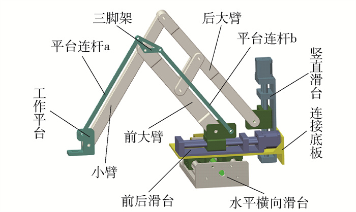
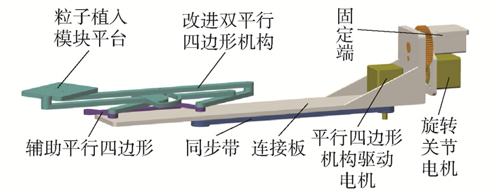
位置调整模块结构如图 3所示. 利用串联双平行四边形机构,来实现末端工作平台固定的水平姿态. 串联双平行四边形机构由图中平台连杆a、b以及三脚架组成.
1.2 姿态调整机构设计
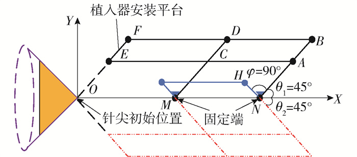
姿态调整机构为改进的2自由度双平行四边形远程运动中心(remote center of motion,RCM)机构[12]. 原理如图 4所示,双平行四边形为▱MNBD、▱ABFE.
为避免机构奇异点,简化驱动源,降低结构质量. 在原有的双平行四边形机构的基础上加入了第3个平行四边形▱MNHG,且保证NH⊥NB. 在X轴方向引入1个旋转自由度,两者配合可实现一定空间椎体范围内的任意姿态调整.
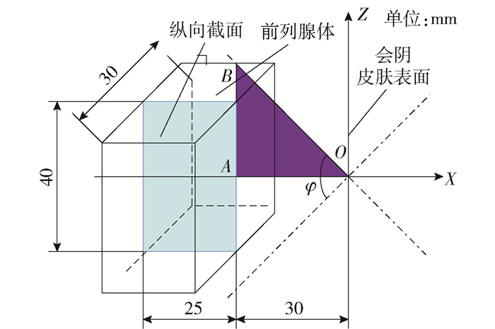
前列腺假定为25mm×30mm×40mm的长方体区域,见图 5,前列腺的最前端距离人体会阴表面距离约为30mm,假设姿态调整模块不动点位于图 5坐标系原点O,为使粒子植入器能覆盖全部前列腺体,φ角必须满足
$$ \varphi>2 \arctan \frac{25}{30} $$ (12) $$ \varphi>79.6^{\circ} $$ (13) 考虑在粒子植入过程中水肿的体积膨胀[13],选取角参数为90°. 姿态调整模块结构见图 6.
1.3 末端植入器设计
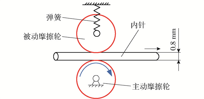
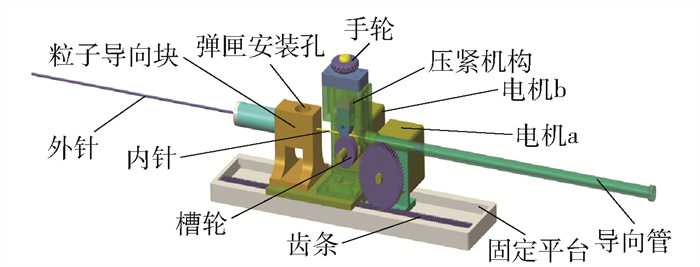
设计采用齿轮齿条机构驱动外针,硬质摩擦槽轮驱动内针,设计一种近似恒定压力的摩擦轮机构,通过弹簧压紧机构来提供稳定压紧力,保证驱动内针的过程中保持稳定的摩擦力,原理如图 7所示,其中,通过精确控制主动摩擦轮的转动角度和圈数加上一定的误差补偿可实现内针进给的精确控制. 植入器的结构模型见图 8.
1.4 弹匣结构设计
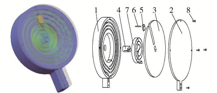
一次粒子植入的用量大约为100~200颗放射性粒子,现有的弹匣结构一般能提供10~20颗放射性粒子. 本文采用盘形轨道结构并由涡卷弹簧提供动力设计了大容量自动粒子弹匣,提高了粒子植入效率. 弹匣模型图如9所示.
2. 运动学分析
文中设计的粒子植入机器人是典型的混联机构. 与一般的串联机构相比,虽然结构存在差异,但是运动学分析的实质是一致的[14],采用D-H法进行运动学求解[15].
2.1 粒子植入机器人正运动学分析
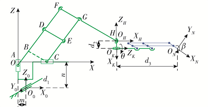
粒子植入机器人机构简图如图 10所示.
基坐标系O0-X0Y0Z0固定在基座上,动坐标系O-XYZ与位置调整模块固连,其他坐标设立如图 10所示. 其中,m、n、d2、d3为常量,由设计要求确定;zA、xC、d1、θ、β为变量,由运动控制要求决定. 将xH、zH、xC、zA理解为变化量,θ、β为相应关节处坐标的回转角度,故式(8)可简化为
$$ \left\{\begin{array}{l} x_{H}=\left(1+\frac{b}{a}\right) x_{C} \\ z_{H}=-\frac{d}{c} z_{A} \end{array}\right. $$ (14) 由于Y0方向滑台独立运动,因此只考虑动坐标系O-XYZ下,ON点的坐标关系.
$$ \left\{\begin{array}{l} x_{H}=x_{H}+d_{3}=\left(1+\frac{b}{a}\right) x_{C}+d_{3} \\ z_{H}=z_{H}-d_{2}=-\frac{d}{c} z_{A}-d_{2} \end{array}\right. $$ (15) 通过齐次坐标变换可知,目标点ON在基坐标系O0-X0Y0Z0下的坐标矩阵表示为
$$ \left(x_{O_{N}}, y_{O_{N}}, z_{O_{N}}, 1\right)^{\mathrm{T}}=\operatorname{Trans}\left(-m, d_{1}, n\right)\left(x_{N}, y_{N}, z_{N}, 1\right)^{\mathrm{T}} $$ (16) 展开后即得到矩阵表达式
$$ \left[\begin{array}{c} x_{O_{N}} \\ y_{O_{N}} \\ z_{O_{N}} \\ 1 \end{array}\right]=\left[\begin{array}{cccc} 1 & 0 & 0 & -m \\ 0 & 1 & 0 & d_{1} \\ 0 & 0 & 1 & n \\ 0 & 0 & 0 & 1 \end{array}\right]\left[\begin{array}{c} \left(1+\frac{b}{a}\right) x_{C}+d_{3} \\ 0 \\ -\frac{d}{c} z_{A}-d_{2} \\ 1 \end{array}\right] $$ (17) 整理得
$$ \left[\begin{array}{c} x_{O_{N}} \\ y_{O_{N}} \\ z_{O_{N}} \\ 1 \end{array}\right]=\left[\begin{array}{c} \left(1+\frac{b}{a}\right) x_{C}+d_{3}-m \\ d_{1} \\ -\frac{d}{c} z_{A}-d_{2}+n \\ 1 \end{array}\right] $$ (18) 粒子植入器的姿态变化为绕X0轴旋转θ角和绕Y0轴旋转β角,得旋转矩阵R为
$$ \boldsymbol{R}_{X_{0}, \theta}=\left[\begin{array}{cccc} 1 & 0 & 0 & 0 \\ 0 & \cos \theta & -\sin \theta & 0 \\ 0 & \sin \theta & \cos \theta & 0 \\ 0 & 0 & 0 & 1 \end{array}\right] $$ (19) $$ \boldsymbol{R}_{Y_{0}, \beta}=\left[\begin{array}{cccc} \cos \beta & 0 & \sin \beta & 0 \\ 0 & 1 & 0 & 0 \\ -\sin \beta & 0 & \cos \beta & 0 \\ 0 & 0 & 0 & 1 \end{array}\right] $$ (20) $$ \boldsymbol{R}=\boldsymbol{R}_{Y_{0}, \beta} \boldsymbol{R}_{X_{0}, \theta}=\left[\begin{array}{cccc} \cos \beta & \sin \theta \sin \beta & \cos \theta \sin \beta & 0 \\ 0 & \cos \theta & -\sin \theta & 0 \\ -\sin \beta & \sin \theta \cos \beta & \cos \theta \cos \beta & 0 \\ 0 & 0 & 0 & 1 \end{array}\right] $$ (21) 因此,机器人末端相对于基坐标的齐次变换矩阵为
$$ \boldsymbol{T}=\left[\begin{array}{cccc} \cos \beta & \sin \theta \sin \beta & \cos \theta \sin \beta & \left(1+\frac{b}{a}\right) x_{C}+d_{3}-m \\ 0 & \cos \theta & -\sin \theta & d_{1} \\ -\sin \beta & \sin \theta \cos \beta & \cos \theta \cos \beta & -\frac{d}{c} z_{A}-d_{2}+n \\ 0 & 0 & 0 & 1 \end{array}\right] $$ (22) 2.2 粒子植入机器人逆运动学分析
由式(18)解得
$$ \left[\begin{array}{l} x_{C} \\ d_{1} \\ z_{A} \end{array}\right]=\left[\begin{array}{c} \frac{x_{O_{N}}+m-d_{3}}{1+\frac{b}{a}} \\ y_{O_{N}} \\ -\frac{c}{d}\left(z_{O_{N}}-n+d_{2}\right) \end{array}\right] $$ (23) 式(23)为前列腺粒子植入机器人的位置逆解.
3. 仿真分析
3.1 运动学仿真
通过ADAMS/View平台进行运动学仿真分析[16-17],输出定位模块末端的运动曲线,验证其在X、Z两个坐标轴方向运动解耦. 驱动添加分为以下2种情况,同时在末端设定2个参考点,基于控制变量原则,分别研究在YOZ平面内Y、Z两方向的运动特点.
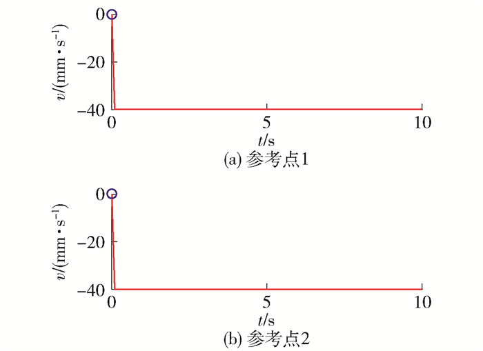
第1种情况:前后电机驱动为step(time, 0, 10, 10, 10),曲线如图 11所示;竖直电机和横向电机的Function(time)选为0,驱动类型Type均选Velocity.
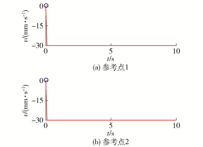
第2种情况:竖直电机驱动为step(time, 0, 10, 10, 10),曲线如图 12所示;前后电机和横向电机的Function(time)选为0,驱动类型Type均选Velocity.
测量仿真模型末端所设置的参考点1、2速度曲线如图 13、14所示. 对比其中参考点1、2的曲线特点可知,式(10)的分析计算结果是正确的,且定位模块在YOZ平面内的解耦,所设计的串联双平行四边形机构可保证该模块运动过程中末端姿态不变.
3.2 动力学仿真
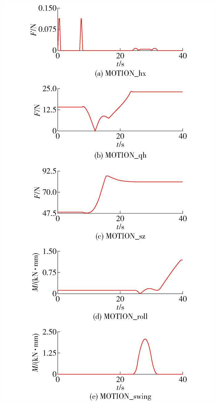
在此只分析位置调整模块和姿态调整模块,假设机器人处于一种手术工作姿态为每一个驱动关节分别、独立运动到极限位置. 由于结构的特点,组织进针动作是由粒子植入器来完成,而位置调整和姿态调整工作在组织进针之前完成,故本节对于位置调整模块和姿态调整模块的分析中不必考虑组织进针的阻力大小,只需考虑末端植入器的重力影响即可,而末端植入器以10N力的形式体现在姿态调整机构的末端. 在5个驱动关节处[18](横向MOTION_hx、前后MOTION_qh、竖直MOTION_sz、滚动MOTION_roll、摆动MOTION_swing)添加驱动力,如图 15所示.
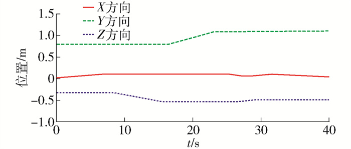
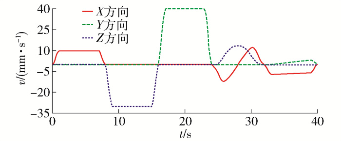
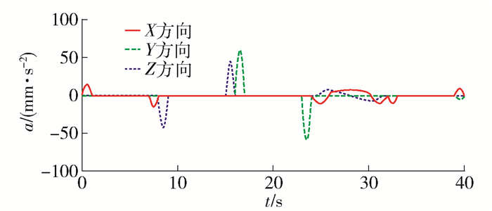
仿真分析后得到姿态调整模块末端零件LINKAGE04的质心点在X、Y、Z三方向的位置曲线见图 16,曲线变化平稳,冲击较小. 速度曲线见图 17,曲线变化平稳与运动协调,无明显冲击,系统运动平稳. 加速度曲线见图 18,曲线变化合理,冲击在可接受范围内,系统运动较平稳. 因此,所设计的结构具有较好的稳定性.
4. 结论
本文设计了一款3P前列腺癌粒子植入机器人,对其进行了正逆运动学分析及仿真分析.
1) 设计了3自由度运动解耦的位置调整模块,并采用了串联双平行四边形机构实现运动过程中姿态不变. 基于改进的平行四边形RCM机构,消除了RCM机构的运动死点. 粒子植入器外针采用齿条驱动,有效地减轻了结构体积;内针采用槽型硬质摩擦轮驱动,准确保证了进针方向和驱动力. 采用盘形轨道结构并由涡卷弹簧提供动力设计了放射性粒子弹匣,与传统弹匣相比增加了容量并减小了结构体积.
2) 采用了改进的D-H法完成了3P前列腺粒子植入机器人的正运动学和逆运动学分析.
3) 以虚拟样机仿真软件ADAMS为分析平台,进行了运动学仿真分析,验证了理论计算分析的准确性、3自由度位置调整模块为运动解耦,并保证了位置调整模块末端平台水平的可靠性. 而动力学分析结果确定了所设计机构的稳定性.
-
-
[1] SIEGEL R L, MILLER K D, JEMAL A. Cancer statistics, 2019[J]. CA: a Cancer Journal for Clinicians, 2019, 69(1): 7-34. doi: 10.3322/caac.21551
[2] YU Y, PODDER T, ZHANG Y, et al. Robot-assisted prostate brachytherapy[C]//Miccai International Conference on Medical Image Computing & Computer-assisted Intervention. Berlin: Springer, 2006: 41-49.
[3] PODDER T K, BUZUROVI I, YU Y. Multichannel robot for image-guided brachytherapy[C]//IEEE International Conference on Bioinformatics and Bioengineering. Piscataway: IEEE, 2010: 209-213.
[4] SALCUDEAN S E, PRANANTA T D, MORRIS W J, et al. A robotic needle guide for prostate brachytherapy[C]//IEEE International Conference on Robotics & Automation. Piscataway: IEEE, 2008: 2975-2981.
[5] VAIDA C, PLITEA N, GHERMAN B, et al. Structural analysis and synthesis of parallel robots for brachytherapy[J]. Journal of Investigative Dermatology, 2014, 115(1): 66-73. http://www.researchgate.net/profile/Calin_Vaida/publication/289069704_Structural_Analysis_and_Synthesis_of_Parallel_Robots_for_Brachytherapy/links/569cda6408ae5c9fe6c012cb/Structural-Analysis-and-Synthesis-of-Parallel-Robots-for-Brachytherapy.pdf
[6] 郭杰, 姜杉, 冯文浩, 等. 基于核磁图像导航的前列腺针刺手术机器人[J]. 机器人, 2012, 34(4): 3-10. https://www.cnki.com.cn/Article/CJFDTOTAL-JQRR201204003.htm GUO J, JIANG S, FENG W H, et al. Robot for prostate acupuncture surgery based on MRI image navigation[J]. Robot, 2012, 34(4): 3-10. (in Chinese) https://www.cnki.com.cn/Article/CJFDTOTAL-JQRR201204003.htm
[7] ZHANG Z, JIANG S, SUN F, et al. Reliability analysis of MRI-guided surgical robot for brachytherapy[J]. IFMBE Proceedings, 2013, 39: 2170-2173 http://or.nsfc.gov.cn/bitstream/00001903-5/143183/1/1000004371630.pdf
[8] 张永德, 梁艺, 毕津滔, 等. 前列腺癌粒子植入机器人运动学建模和仿真[J]. 北京航空航天大学学报, 2016, 42(4): 662-668. https://www.cnki.com.cn/Article/CJFDTOTAL-BJHK201604004.htm ZHANG Y D, LIANG Y, BI J T, et al. Kinematics modeling and simulation of prostate cancer particle implantation robot[J]. Journal of Beijing University of Aeronautics and Astronautics, 2016, 42(4): 662-668. (in Chinese) https://www.cnki.com.cn/Article/CJFDTOTAL-BJHK201604004.htm
[9] 梁艺. 前列腺放射性粒子植入机器人关键技术研究[D]. 哈尔滨: 哈尔滨理工大学, 2017. LIANG Y. Research on key technology of prostate radioactive seed implantation robot[D]. Harbin: Harbin University of Science and Technology, 2017. (in Chinese)
[10] 张震. 前列腺癌微创手术机器人结构设计与控制系统研究[D]. 天津: 天津大学, 2014. ZHANG Z. Research on the structure design and control system of a minimally invasive surgical robot for prostate cancer[D]. Tianjin: Tianjin University, 2014. (in Chinese)
[11] 王晓飞. 1P2R前列腺活检机器人结构设计及仿真[D]. 哈尔滨: 哈尔滨理工大学, 2014. WANG X F. Structural design and simulation of 1P2R prostate biopsy robot[D]. Harbin: Harbin University of Science and Technology, 2014. (in Chinese)
[12] 付宜利, 刘潇, 牛国君, 等. 腹腔微创手术机器人系统远心机构设计与分析[J]. 华中科技大学学报(自然科学版), 2013, 41(增刊1): 289-292. https://www.cnki.com.cn/Article/CJFDTOTAL-HZLG2013S1073.htm FU Y L, LIU X, NIU G J, et al. Design and analysis of telecentric mechanism of minimally invasive abdominal surgery robot system[J]. Journal of Huazhong University of Science and Technology(Natural Science Edition), 2013, 41(Suppl 1): 289-292. (in Chinese) https://www.cnki.com.cn/Article/CJFDTOTAL-HZLG2013S1073.htm
[13] 王彬. 前列腺粒子植入机器人结构设计与分析[D]. 哈尔滨: 哈尔滨理工大学, 2017. WANG B. Design and analysis of the structure of prostate seed implant robot[D]. Harbin: Harbin University of Science and Technology, 2017. (in Chinese)
[14] 王梦. 多自由度串联机器人运动学分析与仿真[D]. 北京: 北京理工大学, 2016. WANG M. Kinematic analysis and simulation of multi-DOF serial robots[D]. Beijing: Beijing Institute of Technology, 2016. (in Chinese)
[15] 杨鲲, 卢倪斌, 隋海琛, 等. 基于D-H方法的波浪滑翔器动力学仿真分析[J]. 哈尔滨工程大学学报, 2020, 41(1): 145-152. https://www.cnki.com.cn/Article/CJFDTOTAL-HEBG202001021.htm YANG K, LU N B, SUI H C, et al. Dynamic simulation analysis of wave glider based on D-H method[J]. Journal of Harbin Engineering University, 2020, 41(1): 145-152. (in Chinese) https://www.cnki.com.cn/Article/CJFDTOTAL-HEBG202001021.htm
[16] 王润. 串联机器人运动学分析、结构优化设计及仿真研究[D]. 天津: 天津大学, 2012. WANG R. Research on the kinematics analysis structural optimization design and simulation of serial robot[D]. Tianjin: Tianjin University, 2012. (in Chinese)
[17] 李凤刚, 赵磊, 何广平, 等. 八自由度连续体操作臂的运动学分析与仿真[J]. 中国机械工程, 2020, 31(16): 1950-1958. https://www.cnki.com.cn/Article/CJFDTOTAL-ZGJX202016008.htm LI F G, ZHAO L, HE G P, et al. Kinematic analysis and simulation of 8-DOF continuous gymnastics arm[J]. Chinese Mechanical Engineering, 2020, 31(16): 1950-1958. (in Chinese) https://www.cnki.com.cn/Article/CJFDTOTAL-ZGJX202016008.htm
[18] 宛云龙, 许红霞. 机器人机械臂动力学仿真研究[J]. 计算机仿真, 2016, 33(12): 346-351. doi: 10.3969/j.issn.1006-9348.2016.12.074 WAN Y L, XU H X. Research on dynamic simulation of robot manipulator[J]. Computer Simulation, 2016, 33(12): 346-351. (in Chinese) doi: 10.3969/j.issn.1006-9348.2016.12.074
-
期刊类型引用(2)
1. 郝颖,张青,郭宏骞. 放射性粒子植入治疗前列腺癌的研究进展. 临床泌尿外科杂志. 2024(02): 161-166 .  百度学术
百度学术
2. 潘剑,梁超,谢欣. 多元化正向情感唤醒护理对全麻前列腺癌手术患者应激反应及麻醉恢复的影响. 中国医药导报. 2023(30): 173-176 .  百度学术
百度学术
其他类型引用(1)


 下载:
下载:
