
Radius Design of Acetabulum on Hip Prostheses With Dynamic Edge Contact
-
摘要:
当髋关节假体部件侧向移动足够大的距离接触到髋臼杯边缘时,带状磨损就会发生,为改善这种带状磨损导致的局部异常高接触应力现象,研究应用经典Hertzian接触理论对髋关节的边缘半径进行设计计算,分析不同髋臼倾角的法向载荷作用下接触尺寸和最大接触应力及合理的边缘半径等重要参数.计算结果表明:随着边缘半径的增加,髋臼倾角在2°~50°内,起初最大接触压力小幅降低,随后缓慢增加,最终趋于稳定,可取得极小接触压力;而在倾角50°以上情况下最大接触压力迅速增长,边缘半径需较大变化才能取得极小接触压力.随着倾角变化极小压力边缘半径先减小后趋于稳定后达到最小值,在45°之后急剧增大.在相同的条件下接触尺寸和最大接触压力将随着载荷的增加而增加.随着髋臼倾角的增加,接触尺寸将减小,而最大接触压力将增大.通过该数值计算方法有助于寻找到合适的边缘半径,从而能更好地降低髋臼杯边缘接触压力,改善其应力分布规律,减轻带状磨损现象,以延长人工髋关节使用寿命.
Abstract:When the components of hip prostheses move a sufficient distance laterally to contact the edge of the acetabular cup, causing abnormally high contact stresses, the contact dimensions and maximal contact pressure with appropriate edge radius were investigated based on classical Hertzian contact theory. The computational results show that with the increase of the edge radius of the hip, the angle of acetabulum within the range of 2°-55° first decreases slightly, then slowly increases, and eventually tends to be stable to obtain the minimal contact pressure. While the angle over 50° contact pressure increases rapidly and the large change of edge radius of hip is needed to obtain the minimal contact pressure. With the change of the acetabulum angle, the radius of the pressure edge decreases first and then reaches a minimum, and there is a sharp increase after reaching 45°. The edge radius of hip bearings is designed to find contact size and the maximum contact pressure are proportional to loading under the same condition. The increased angle of cup inclination reduces contact size while enlarges the maximum contact pressure. The appreciate radius using this contact theory better resist severe edge loading contact stresses for reducing the stripe wear. This can prolong the lifetime of the hip prostheses.
-
Keywords:
- hip prostheses /
- dynamic contact /
- edgeradius /
- contact pressure /
- Hertz contact theory /
- biomechanics
-
人工髋关节置换手术的患者人数不断上升且患者趋于年轻化,除了外科手术技巧外,目前国内外学者们的研究注重于延长人工关节的使用寿命、假体精确定位等方面的问题[1-2].由于各种并发症、假体松动等因素使得全髋关节翻修术复杂且非常困难,因此,更完善的初次翻修术就显得格外重要.
人工关节的磨损问题始终是人们关注的焦点,不仅是当前医学及生物力学领域研究的一个热点问题,也已引起机械工程领域学者们的极大关注[3-6].人工关节的磨损与关节接触面压力的分布状况相关[7-8].特别是,边缘接触过程中的力学状态及接触行为,会直接影响人工髋关节轴承表面相对运动与磨损.因此,研究人工髋关节边缘接触也是认识关节磨损机理问题的重要内容.
不具理想设计的球-座关节功能的髋臼杯和股骨头会加重磨损.研究表明,材料为聚合物对金属的人工髋关节存在较大的磨损量,磨损产生磨损粒子是导致生物组织反应主要原因[1, 4].此外,若髋关节假体运动幅度过大,使得关节股骨头与髋臼边缘接触,从而导致高边缘接触压力和进一步附加磨损问题出现[9-10].关节接触面压力的分布状况决定了人工关节润滑及磨损性能,因此,在全髋关节置换术中,股骨头半径、髋臼倾角等设计参数对关节的接触压力分布有着重要的影响.
临床上发现,相对垂直的髋臼杯定向可能导致边缘加载,而且近来临床研究发现在1 884例假体中有34%的髋臼杯外展角在45°以上[1-2].实验表明,非共轴小接触面积边缘载荷下,髋臼倾角过大或过小都可能导致边缘接触行为.较大髋臼倾角下,相对股骨头较大倾斜状态极易引起不同的边缘接触现象,会导致临床外科和关节制造上的困难[9-10],还会发生微分离诱导的带状磨损现象[11-12].而在小髋臼倾角时,虽然理想的同轴载荷下,球和座处于协调接触,其接触表面半径接近匹配,接触面积大、接触应力低,而非共轴载荷下小接触面积边缘载荷却会产生较高的接触应力,且接触半径不同[13-14].从协调球面接触到非协调圆环的接触变化将增加假体接触应力,目前解决这类问题的可能方案是变更材料和合理地设计髋臼结构.由于现已证明铝和氧化锆的复合陶瓷材料比纯铝具有更大程度的抵抗微分离磨损性能[8-9],因此应用这类材料的基体结构设计依然是当今人工髋关节置换装置设计面临的关键.
本文将应用经典Hertizan接触理论[10-11],通过动态接触离散方法,求解接触尺寸和最大接触压力,从而分析极小接触压力,确定髋臼结构边缘半径.通过合适的边缘半径设计来降低接触应力,为年轻髋关节患者的髋关节翻修术临床外科和人工髋关节制造中良好地控制人工髋关节的非球性、优化髋关节接触面匹配程度、改善关节的接触压力分布提供依据.
1. 髋臼边缘模型与接触参数计算方法
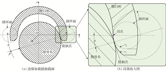
髋臼边缘的圆环表面如图 1所示.
![]()
圆环面在笛卡儿坐标系Oxyz中的参数化方程为
$$ \left\{\begin{array}{l}{x=\left(R_{0}+r_{0} \cos v\right) \cos u} \\ {y=\left(R_{0}+r_{0} \cos v\right) \sin u} \\ {z=r_{0} \sin v}\end{array}\right. $$ (1) 式中:R0和r0分别为圆环的大半径和小半径;u为关于圆环大半径的角度;v为关于圆环小半径的角度.
如图 2所示,股骨头和髋臼杯边缘之间的接触模拟为球-圆环接触.
![]() 图 2 边缘加载接触截面和局部放大图Figure 2. Model schematic diagram of edge-loaded contact in the cross section and the partial enlarged drawing
图 2 边缘加载接触截面和局部放大图Figure 2. Model schematic diagram of edge-loaded contact in the cross section and the partial enlarged drawing$$ \left\{\begin{array}{l}{k_{11}=H-\sqrt{H^{2}-K}} \\ {k_{11}=H+\sqrt{H^{2}-K}}\end{array}\right. $$ (2) 式中:K为高斯曲率;H为平均曲率.
根据圆环参数方程式(1),它们分别为
$$ \left\{\begin{array}{l}{K=\frac{\cos v}{r_{0}\left(R_{0}+r_{0} \cos v\right)}} \\ {H=\frac{R_{0}+2 r_{0} \cos v}{2 r_{0}\left(R_{0}+r_{0} \cos v\right)}}\end{array}\right. $$ (3) 若设图 2中髋臼杯倾角θ, 那么可得到v=π+θ,再将式(3)代入方程式(2)得
$$ \left\{\begin{array}{l}{k_{11}=\frac{1}{-R_{0} \times \sec \theta+r_{0}}} \\ {k_{12}=\frac{1}{r_{0}}}\end{array}\right. $$ (4) 假设:1)材料是均匀、线弹性、各向同性的,而且在共心接触中表面完全光滑无摩擦;2)表面是非协调的;3)在接触点处接触尺寸相对于接触表面半径足够小.根据赫兹接触理论,接触椭圆的尺寸与接触表面有关,其关系式[12]为
$$ \frac{\left(1-e^{2}\right)^{-1} E(e)-K(e)}{K(e)-E(e)}=\frac{\varSigma+\varDelta}{\varSigma-\varDelta} $$ (5) 其中
$$ \left\{\begin{aligned} \varSigma=& k_{11}+k_{12}+k_{21}+k_{22} \\ \varDelta=&\left[\left(k_{11}-k_{12}\right)^{2}+\left(k_{21}-k_{22}\right)^{2}+\right.\\ &\left.2\left(k_{11}-k_{12}\right)\left(k_{21}-k_{22}\right) \cos (2 \beta)\right]^{1 / 2} \\ e=& \sqrt{1-b^{2} / a^{2}} \end{aligned}\right.\ $$ (6) 式中:k21=k22是球面的主曲率,而且因为接触表面是球面,所以坐标变换角β=0;e称为椭圆偏心率;a、b分别为接触椭圆的长半轴和短半轴;K(e)、E(e)分别为关于e的第1类和第2类完全椭圆积分[11-12],其方程为
$$ \left\{\begin{array}{l}{K(e) \equiv \int_{0}^{{\rm{ \mathsf{ π} }} / 2} 1 / \sqrt{1-e^{2} \sin ^{2} \phi} \mathrm{d} \phi} \\ {E(e) \equiv \int_{0}^{{\rm{ \mathsf{ π} }} / 2} \sqrt{1-e^{2} \sin ^{2} \phi} \mathrm{d} \phi}\end{array}\right. $$ (7) 因为它们是一个由高等超越积分函数组成的超越方程,所以e只能通过数值计算得到.
由赫兹积分公式,导出接触椭圆尺寸的2个公式
$$ \left\{\begin{array}{l}{a=\left\{\frac{6 P[K(e)-E(e)]}{{\rm{ \mathsf{ π} }} e^{2} E^{*}(\varSigma-\varDelta)}\right\}^{1 / 3}} \\ {b=\left\{\frac{6 P \sqrt{1-e^{2}}\left[E(e)-\left(1-e^{2}\right) K(e)\right]}{{\rm{ \mathsf{ π} }} e^{2} E^{*}(\varSigma+\varDelta)}\right\}^{1 / 3}}\end{array}\right. $$ (8) 接触体的杨氏模量E1、E2和泊松比为ν1、ν2存在的关系式和最大接触压力[8]为
$$ E^{*} =\left[\left(1-\nu_{1}\right) / E_{1}+\left(1-\nu_{2}^{2}\right) / E_{2}\right]^{-1} $$ (9) $$ p_{0}=\frac{3 P}{2 {\rm{ \mathsf{ π} }} a b} $$ (10) 本文动态模拟人工髋关节在给定生理位移工况条件下的接触行为和相应的边缘接触现象,如图 2所示,在股骨头和具体的髋臼杯边缘之间创建动态接触.计算中需要的有关材料特性和物理条件列在表 1[7-9]中.给定边缘半径r在0~80 000的一系列离散值,应用式(4)(6)进行Mathematica编程数值求解方程式(5)可得到一系列椭圆偏心率e,将e代入式(7)(8)中可得一系列接触尺寸和最大接触压力,再比较最大接触压力,称最小的最大接触压力为极小接触压力,此时取得极小接触压力所对应的边缘半径称为极小压力边缘半径rmin.
名称 符号 数值 股骨头半径 Rh/mm 14 髋臼内部半径 Rc/mm 14.1 股骨头杨氏模量 Eh/GPa 230 髋臼杨氏模量 Ec/GPa 300 股骨头泊松比 νh 0.3 髋臼泊松比 νc 0.26 法向载荷 P/N 0~3 000 倾角 θ 见表 2 圆环半径 r0/mm 0~80 000 圆环轴半径 R0=(r0+Rc)/mm 28.1 表 2 不同倾角时取得极小接触压力的边缘半径Table 2. Minimal contact pressure and edge radius of different inclination anglesθ/(°) p0/MPa r/mm 2 1 311.80 90 8 1 843.50 38 13 2 198.07 34 15 2 323.08 32 20 2 603.31 32 25 2 845.45 32 32 3 130.34 34 40 3 384.54 42 47 3 544.72 60 55 3 650.82 135 60 3 670.63 80 000 65 3 670.68 80 000 72 3 670.74 80 000 80 3 670.79 80 000 2. 计算与结果
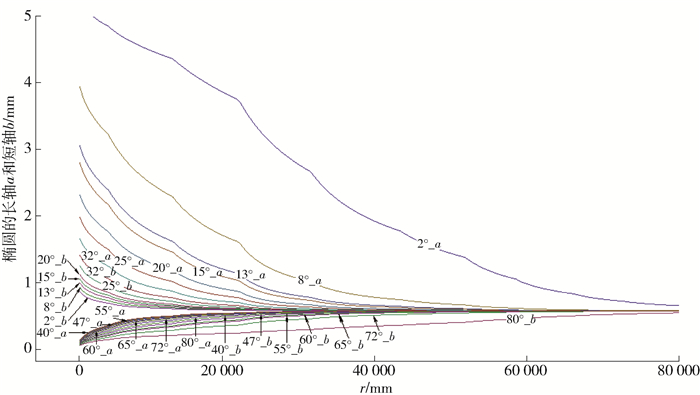
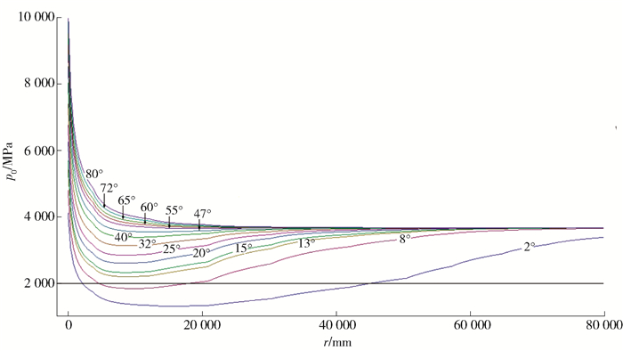
髋臼杯边缘的接触参数如图 3、4所示. 图 3显示在不同的边缘半径,随载荷的变化接触尺寸和最大接触压力的变化规律,同时给出在多种倾角(2°、8°、13°、15°、20°、25°等)的变化下的关系.当载荷是2 500 N且倾角为20°时,随着边缘半径的变化接触尺寸和最大接触压力的变化规律如图 4所示. 表 2总结了考虑多种倾角时取得极小接触压力时的边缘半径,并拟合数据绘制规律曲线,如图 5所示.总体上,在相同的条件下接触尺寸和最大接触压力将随着载荷的增加而增加后趋于稳定;随着髋臼倾角的增加,接触尺寸将减小,而最大接触压力将增大.
![]() 图 3 不同边缘半径下的接触半轴a和bFigure 3. Elliptical major semi-axis(a) and elliptical minor semi-axis(b) in dynamic edge radius
图 3 不同边缘半径下的接触半轴a和bFigure 3. Elliptical major semi-axis(a) and elliptical minor semi-axis(b) in dynamic edge radius![]() 图 5 不同极小接触压力(1 500~4 000 MPa)所对应的边缘半径Figure 5. Minimal contact pressure of the edge radius with the minimal contact pressure from 1 500 MPa to 4 000 MPa
图 5 不同极小接触压力(1 500~4 000 MPa)所对应的边缘半径Figure 5. Minimal contact pressure of the edge radius with the minimal contact pressure from 1 500 MPa to 4 000 MPa2.1 不同边缘圆环半径下的接触尺寸和最大接触压力
如图 3所示,在弹性范围内接触区是椭圆,长轴a和短轴b遵循赫兹理论计算的趋势;在边缘半径r在2~80 000 mm内变化,椭圆长轴a逐渐减少,而椭圆短轴b逐渐增大.考虑到人工髋臼在各种行走姿态下倾角在较大范围内的变化,将倾角设定为2°~80°.当在相同的边缘半径前提下,髋臼倾角从2°到80°变化时,椭圆长轴a变小,而椭圆短轴b增大.
如图 4所示,随着上述边缘半径r的增加,在大部分髋臼倾角(2°~55°)情况下,起初最大接触压力迅速降低,然后又缓慢增加,趋于稳定.这说明存在一个最低的最大接触压力,称之为极小接触压力;而在其他倾角下最大压力变化并非如此,在少部分倾角(60°~80°)情况下最大接触压力起初迅速降低,然后缓慢降低,然后趋于稳定.如果边缘半径相同,随着髋臼倾角的降低最大接触压力出现降低,在髋臼倾角为2°时,出现极小的最大接触压力值.在图 4中每一条曲线在降低和增加之间均存在一个最低点.有趣的是取得极小接触压力时所对应的边缘半径r,经Hertizan接触理论计算,如表 2所示,表中的边缘半径能有效地降低接触应力,这有助于降低刮擦带状磨损.该结论为体外研究中观察到的低稳态磨损率提供了理论支持.
2.2 极小接触压力下的边缘半径
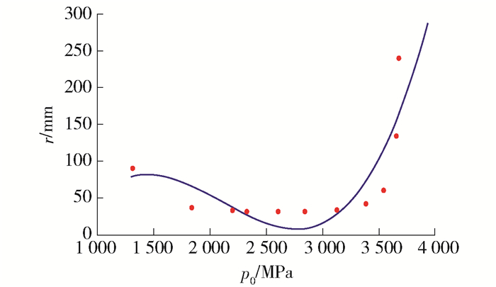
将表 2中的压力和半径数据进行非线性多项式拟合,得到极小压力边缘半径与极小压力的关系式
$$ \begin{array} [c]{c} r_{\min P}=-384.405+0.780 \;542 p_{0}-\\ 0.000\;410\;586 p_{0}^{2}+6.498\;15 \times 10^{-8} p_{0}^{3} \end{array} $$ (11) 将式(11)绘于图 5中,红点为表 2中的离散点,蓝线为拟合曲线.可看出1 500~4 000 MPa的极小接触压力下动态接触时边缘半径随最大接触压力的变化规律.当极小接触压力在1 500~2 700 MPa时接触半径有小幅减小;在2 700~3 500 MPa时接触半径开始增加;当极小接触压力超过3 500 MPa时边缘半径迅速增加.
再将表 2中的倾角和半径数据进行非线性多项式拟合,从而可得到极小压力边缘半径与倾角的关系式
$$ \begin{array} [c]{c} r_{\text {min }\theta}= 114.514-14.705\;8 \theta+0.895\;593 \theta^{2}-\\ 0.022\;571\;6 \theta^{3}+0.000\;205\;133 \theta^{4} \end{array} $$ (12) 将式(12)绘于图 6中,可观察出动态接触时边缘半径随倾角的变化趋势.在倾角较小时随着边缘半径显著变化取得极小接触压力;当倾角在10°~50°时边缘半径变化较小即可取得极小接触压力;而当倾角大于50°时,边缘半径需较大变化才能取得极小接触压力.倾角在10°~40°时极小压力边缘半径趋于平稳且处于半径较小阶段.
![]() 图 6 不同极小接触压力(0~60 MPa)所对应的边缘半径Figure 6. Minimal contact pressure of the edge radius with the minimal contact pressure from 0 MPa to 60 MPa
图 6 不同极小接触压力(0~60 MPa)所对应的边缘半径Figure 6. Minimal contact pressure of the edge radius with the minimal contact pressure from 0 MPa to 60 MPa3. 结论
1) 随边缘半径的增加,当髋臼倾角在2°~50°情况下,起初最大接触压力迅速降低,随后又缓慢增加,最终趋于稳定,可取得极小接触压力;而当倾角大于50°时最大接触压力起初迅速增长,边缘半径需较大变化才能取得极小接触压力.
2) 随着倾角变化极小压力边缘半径先减小后趋于稳定后达到最小值,45°之后急速增大.
3) 本研究的结果有助于体外降低磨损研究中改进边缘半径设计,更好地降低边缘接触应力,改善应力分布,减轻带状磨损,延长人工髋关节使用寿命.
-
![]()
![]()
图 2 边缘加载接触截面和局部放大图
Figure 2. Model schematic diagram of edge-loaded contact in the cross section and the partial enlarged drawing
![]()
图 3 不同边缘半径下的接触半轴a和b
Figure 3. Elliptical major semi-axis(a) and elliptical minor semi-axis(b) in dynamic edge radius
![]()
图 5 不同极小接触压力(1 500~4 000 MPa)所对应的边缘半径
Figure 5. Minimal contact pressure of the edge radius with the minimal contact pressure from 1 500 MPa to 4 000 MPa
![]()
图 6 不同极小接触压力(0~60 MPa)所对应的边缘半径
Figure 6. Minimal contact pressure of the edge radius with the minimal contact pressure from 0 MPa to 60 MPa
名称 符号 数值 股骨头半径 Rh/mm 14 髋臼内部半径 Rc/mm 14.1 股骨头杨氏模量 Eh/GPa 230 髋臼杨氏模量 Ec/GPa 300 股骨头泊松比 νh 0.3 髋臼泊松比 νc 0.26 法向载荷 P/N 0~3 000 倾角 θ 见表 2 圆环半径 r0/mm 0~80 000 圆环轴半径 R0=(r0+Rc)/mm 28.1  下载: 导出CSV
表 2 不同倾角时取得极小接触压力的边缘半径
Table 2 Minimal contact pressure and edge radius of different inclination angles
θ/(°) p0/MPa r/mm 2 1 311.80 90 8 1 843.50 38 13 2 198.07 34 15 2 323.08 32 20 2 603.31 32 25 2 845.45 32 32 3 130.34 34 40 3 384.54 42 47 3 544.72 60 55 3 650.82 135 60 3 670.63 80 000 65 3 670.68 80 000 72 3 670.74 80 000 80 3 670.79 80 000
下载: 导出CSV
-
[1] HOTHAN A, HUBER G, WEISS C, et al. The influence of component design, bearing clearance and axial load on the squeaking characteristics of ceramic hip articulations[J]. Journal of Biomechanics, 2011, 44(5):837-841. doi: 10.1016/j.jbiomech.2010.12.012
[2] HUA X, LI J, JIN Z, et al. The contact mechanics and occurrence of edge loading in modular metal-on-polyethylene total hip replacement during daily activities[J]. Medical Engineering & Physics, 2016, 38:518-525. http://cn.bing.com/academic/profile?id=7960ec5bfbe908b5930b1f0c041d849e&encoded=0&v=paper_preview&mkt=zh-cn
[3] BROCKETT C, WILLIAMS S, JIN Z, et al. Friction of total hip replacements with different bearings and loading conditions[J]. Journal of Biomedical Materials Research Part B Applied Biomaterials, 2007, 81:508-515. http://cn.bing.com/academic/profile?id=c0c88a54ae34544eb7a572b68add2691&encoded=0&v=paper_preview&mkt=zh-cn
[4] KWON Y M, MELLON S J, MONK P, et al. In vivo evaluation of edge-loading in metal-on-metal hip resurfacing patients with pseudotumours[J]. Bone & Joint Research, 2012, 1(4):42-49. http://d.old.wanfangdata.com.cn/OAPaper/oai_pubmedcentral.nih.gov_3626206
[5] HALMA J J, SEÑARIS J, DELFOSSE D, et al. Edge loading does not increase wear rates of ceramic-on-ceramic and metal-on-polyethylene articulations[J]. Journal of Biomedical Materials Research Part B Applied Biomaterials, 2014, 102:1627-1638. doi: 10.1002/jbm.b.33147
[6] BELL C J, INGHAM E, FISHER J. Influence of hyaluronic acid on the time-dependent friction response of articular cartilage under different conditions[J]. Proceedings of the Institution of Mechanical Engineers, Part H, Journal of Engineering in Medicine, 2006, 220(1):23-31. doi: 10.1243/095441105X69060
[7] WANG F C, WANG L S, SUN M L. Tribological modelling of spherical bearing with complex spherical-base geometry and motion[J]. WIT Transactions on Engineering Sciences, 2010, 66:3-15. http://cn.bing.com/academic/profile?id=f5c5690d58784425d18e7a973d5e49cc&encoded=0&v=paper_preview&mkt=zh-cn
[8] ANTHONY P S, REBECCA M B. Assessment of the applicability of the Hertzian contact theory to edge-loaded prosthetic hip bearings[J]. Journal of Biomechanics, 2011, 44:2802-2808. doi: 10.1016/j.jbiomech.2011.08.007
[9] YAMAMOTO T, SAITO M, UENO M, et al. Wear analysis of retrieved ceramic-on-ceramic articulations in total hip arthroplasty:femoral head makes contact with the rim of the socket outside of the bearing surface[J]. Journal of Biomedical Materials Research Part B Applied Biomaterials, 2005, 73:301-307. http://cn.bing.com/academic/profile?id=d5f7dc36251f5d021e1487831aea79e2&encoded=0&v=paper_preview&mkt=zh-cn
[10] ALI M, MAO K. Contact analysis of hip resurfacing devices under normal and edge loading conditions[J]. IAENG Special Issues Journal, 2012, 20(4):317-329. http://d.old.wanfangdata.com.cn/OAPaper/oai_doaj-articles_ba11a6d8bb4ab7384943303044d28afb
[11] LIU F, FISHER J. Effect of an edge at cup rim on contact stress during micro-separation in ceramic-on-ceramic hip joints[J]. Tribology International, 2017, 113:323-329. doi: 10.1016/j.triboint.2017.01.012
[12] NIKAS G K. Fatigue life and traction modeling of continuously variable transmissions[J]. Journal of Tribology-Transactions of the ASME, 2002, 124:689-698. doi: 10.1115/1.1491976
[13] LIU F, WILLIAMS S, FISHER J. Effect of microseparation on contact mechanics in metal-on-metal hip replacements-A finite element analysis[J]. Journal of Biomedical Materials Research Part B Applied Biomaterials, 2014, 103:1312-1319. http://www.wanfangdata.com.cn/details/detail.do?_type=perio&id=2e124b11f96402c71da062e50cf057fd
[14] WANG F C, JIN Z M. Transient elastohydrodynamic lubrication of hip joint implants[J]. Journal of Tribology-Transactions of the ASME, 2008, 130(1):125-128. doi: 10.1115-1.2806200/
-
期刊类型引用(0)
其他类型引用(1)


计量
- 文章访问数: 202
- HTML全文浏览量: 2
- PDF下载量: 54
- 被引次数: 1
